Go to the Yamaha DX7s main page
After around twenty years faithful service, the battery in my Yamaha DX7s finally gave up the ghost at the end of 2009. I looked around the web and found several really helpful sites and pages (see Further information at the foot of this page). However, I found some discrepancies between the descriptions available on the web and the construction of my own Yamaha DX7s (e.g. the number of screws holding the base on and which screws have to be removed etc). I decided to document the process, as it worked for me, and stick it on the web.
You can check the voltage of the installed battery in a DX7s by switching the synthesizer on and pressing the following keys together: 'EDIT' + '16' + '32'. This will display the first screen of the internal diagnostics.The battery voltage display can be cancelled by pressing the 'VOICE' button. You can find out more on my How to run the Yamaha DX7s internal diagnostics page.
The procedure I opted for involved replacing the soldered-on battery with an easily accessible battery holder. I also wanted to ensure that the whole process was non-destructive and reversible, with no requirement to drill, cut, glue or modify any part of the DX7s.
PLEASE NOTE:
I accept no responsibility for any loss or damage to yourself, any of your property, including your Yamaha
DX7s, or anything or anyone else, which may arise from you following the procedure detailed on this page.
You do so entirely at your own risk.
There appear to be two main differences between the CR2032 'coin cell' battery in a Yamaha DX7 and a standard CR2032:
I decided that, notwithstanding the twenty year battery life, I'd replace the solder-on battery with a battery holder and standard cell. When I discovered the location of the factory-installed battery, I also decided to run leads from the motherboard to a more accessible location.
Having decided on the 'easy access battery holder' approach, I didn't feel so bad about installing a battery which may not last as long as its predecessor. Having said that, as of May 2019 my replacement battery is still doing its job, ten years after being installed.
I'm based in the UK, where Radio Shack (known as 'Tandy' over here) no longer exists. I sourced my components from Maplin, who offered similar products and services. Maplin went out of business in June 2018 and re-launched on-line in January 2019. However, they don't appear to offer the same range of components any more. I suggest trying a web search for 'hobbyist electronic components', to locate a suitable supplier. Here's what I used:
Depending on the type of battery lead you use, you may also require soldering pins. You'll also require a means of mounting your new battery holder board. I just used a thin cable-tie:
My plan was to solder two leads to the motherboard battery terminals, run the leads out to an accessible location within the keyboard case and solder the other ends to a battery holder, mounted on a small circuit board.
You'll need:
Also, the following items aren't absolutely essential, but would be helpful:
The chances are that, even though your Yamaha DX7s display shows the message 'Replace Battery!', the battery itself is still providing some power and keeping your custom voices, patches etc. alive. If you have programmed any custom voices, patches, performance data, or anything else into your DX7s, you must back it up (e.g. with a PC / Mac librarian utility).
I recommend you remove any cartridge you may have in the DX7s catridge slot. If you don't do this, the cartridge connector and / or the circuit board could be damaged when you turn the DX7s over. Before inserting or removing a ROM or RAM cartridge, make sure your DX7s is switched off. Changing cartridges with the synthesizer switched on can result in permanent damage.
In addition to being switched off, your DX7s should have its power lead unplugged from the mains electricity supply. Failure to do this before commencing the procedure detailed on this page could result in electrocution and death (of you and / or your DX7s).
Tap any image to enlarge it.
Please note: The screws, which hold the base on come in several different sizes and lengths; make sure you note which holes they came out of; it will save you a lot of time when you reassemble your DX7s.
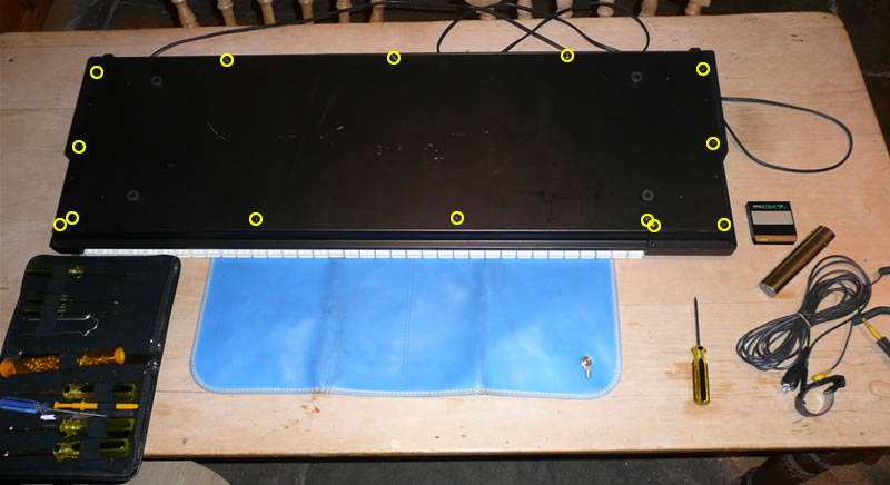
Yamaha DX7s upside-down with screws to be removed circled in yellow
The blue mat in the image is part of an anti-static kit, used with the earthing cables in the bottom right hand corner of the image. An anti-static kit isn't essential, but you should take adequate anti-static precautions.
There are fourteen screws holding the base on the Yamaha DX7s. Unscrew them all and then lift and tilt the back of the base (at the top of the image) upwards and forwards (towards the front of the keyboard); it should hinge up along the front edge above the white key undersides and slide forward and off.
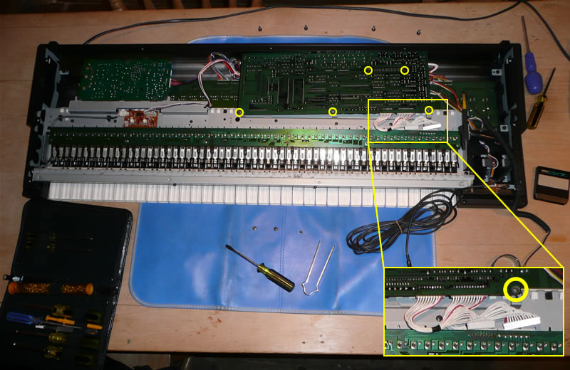
Base removed with motherboard screws to be removed circled in yellow. Inset shows edge connectors detached.
The next job is to release the motherboard. I found it wasn't necessary to remove it completely, which saves a lot of fiddling around with edge connectors and cables. The motherboard is secured with three screws securing the board to the metal chassis (the three lower circled points in the image above), two screws holding it to mounting posts (the upper two circled points in the image above) and four screws on the back of the keyboard (shown in the image below). Remove all these screws and detach the two edge connectors, which link the motherboard to the long circuit board under the keyboard keys. Care needs to be used when removing the edge connectors, as the pins can be bent; I used a pair of edge connector tweezers, but gentle use of thin nosed pliers, or a small, flat bladed screwdriver should also work.
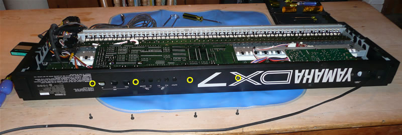
Rear view with motherboard screws to be removed circled in yellow
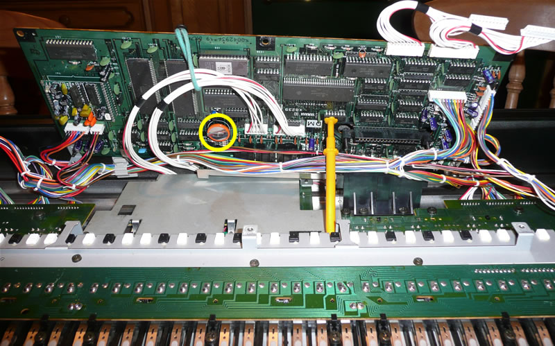
Underside of motherboard with battery circled in yellow
Lift the motherboard up and secure it in the raised position. I used a non-metallic probe (the yellow syringe-like thing sticking up, just right of centre in the image above). I also tied back the cables from the two edge connectors in the centre of the motherboard; this gave me a better view of and easier access to the battery.
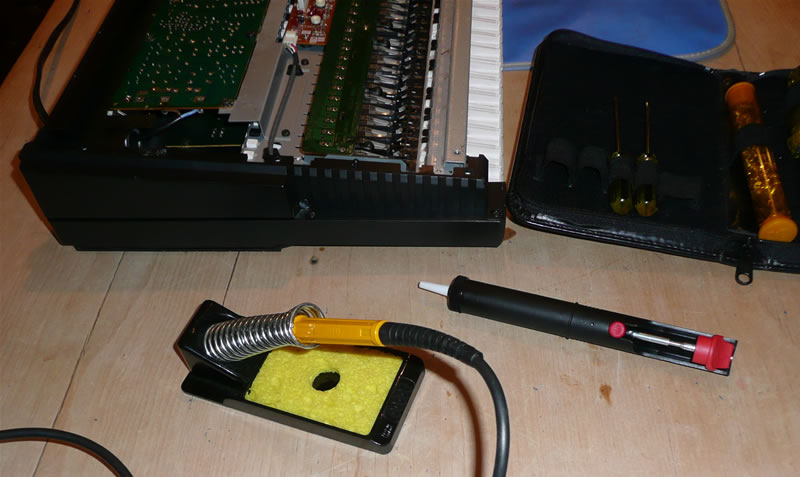
A soldering iron and solder-sucker used for battery removal and replacement
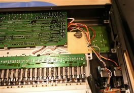
If you haven't already done so, now would be a good time to plug your soldering iron in and locate your solder-sucker or de-soldering braid. Remove as much of the solder as possible from the battery terminals on the underside of the motherboard (see the image below for the exact locations of the de-soldering points).
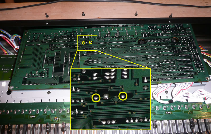
The battery contacts viewed from the motherboard underside
If, after de-soldering, the battery can't be removed from the motherboard, try a very gentle levering action, using a non-metallic lever between the battery and motherboard, whilst applying the soldering iron tip to each of the battery terminal points (on the other side of the motherboard) in turn.
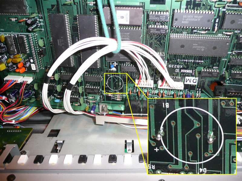
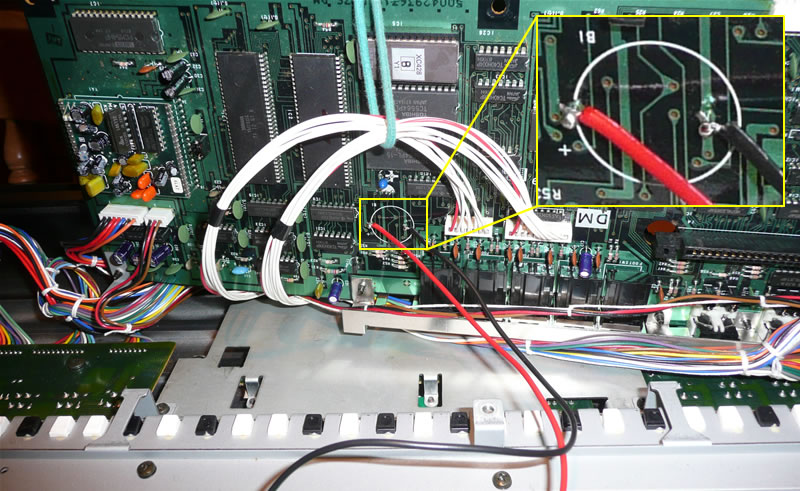
Location of battery lead soldering pins
NOTE: Before commencing this step, note the location of the positive battery terminal on the motherboard. It's marked with a '+' sign on the motherboard itself and is the left-hand terminal in the images above and below in this step.
Depending on the gauge of your battery leads, you may be able to feed the stripped and tinned ends directly through the de-soldered holes in the motherboard, from the battery side. If you can't do this, you can use two soldering pins. I improvised these by tinning two steel dress-making pins with solder, pushing them through the holes in the motherboard, soldering them in place and then snipping off the excess with wire cutters. I pushed the pins through from the battery side of the motherboard, leaving the pin-heads available for battery lead attachment. Whether you use the bare wires, or soldering pins, they should be soldered in place from the underside (non battery side) of the motherboard.
Battery leads soldered to soldering pins
If you use soldering pins, tin the attached soldering pins and then solder the stripped and tinned battery leads to them. I used a red lead for the positive terminal and black for the negative terminal.
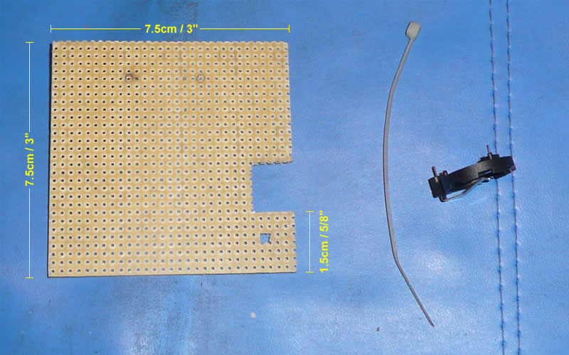
Battery holder and board with approximate dimensions
To mount the battery holder, I used a small piece of plain, drilled electronics board (often referred to as vero board, after the 'Veroboard' product). This has pre-drilled holes in a standard grid, with 2.5mm spacing. Most standard board-mounting electronic components, including the CR2032 battery holder, should fit this board directly, without any modification or pin bending. I cut the board to fit my chosen location within the DX7s case. It includes a cut-out to accommodate part of the existing wiring loom, without the need to cut the original cable tie. It also has a small hole drilled in it (visible in the bottom right hand corner of the board, below the cut-out, in the image above). The above image shows the board, with approximate measurements, the cable tie used for securing it to the DX7s chassis and the battery holder itself (shown edge-on so you can see the board-mounting pins).
Battery leads attached to the battery board underside. Board mounting hole circled in yellow.
Route the battery leads under the motherboard to the selected battery board location and then re-attach the motherboard with all the screws you removed in step 2. Cut the leads to length, leaving plenty of spare for positioning and fitting the battery board. Strip and tin the ends of the battery leads with solder, ready for installation. I pushed the leads through holes in the board for the images above and below in this step, to indicate the correct position of the positive and negative pins, but for the actual installation, they were soldered directly onto the battery holder pins, on the underside of the board.
The image above shows the hole I used for securing the battery board to the DX7s chassis circled in yellow.
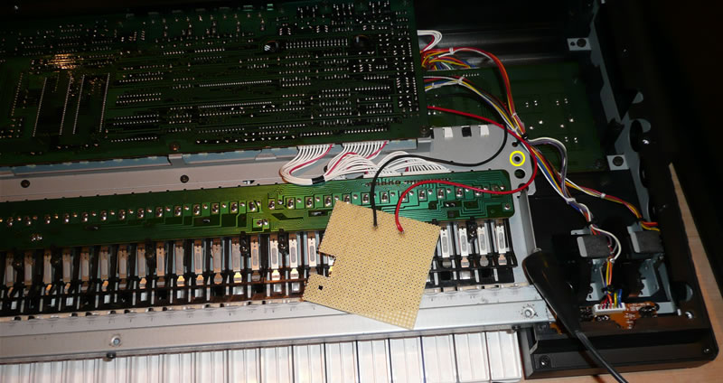
Battery board with battery leads attached
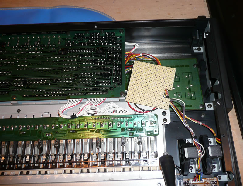
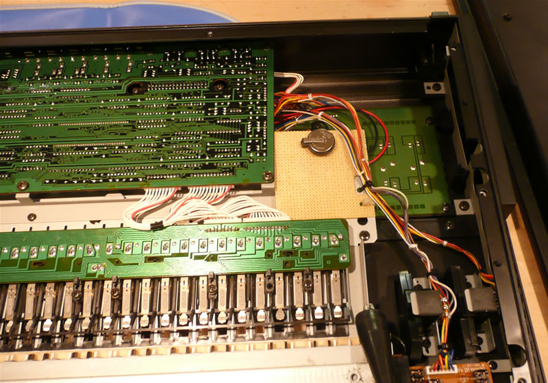
Battery holder and board installed
NOTE: This exact procedure may vary, depending on the type of battery holder you have; this description is based on the installation of my pin-through-board mounting holder.
Position the battery holder in the centre of the upper part of the battery board (see the above image) and push the pins through the holes in the board. Tin the protruding pins on the underside of the board, before soldering the battery leads to them. Make sure the positive lead is soldered to the terminal, which will contact the top and edge of the CR2032 battery. The negative terminal contacts the underside of the battery.
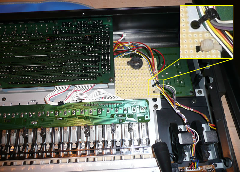
Once the battery holder and leads are soldered and in place, position the board under the cables of the existing wiring loom and secure it with the cable tie, as shown in the above image.
Battery installed in battery holder
That's pretty much it. All you need to do now is fit a new battery in your installed battery holder and put your Yamaha DX7s back together, reversing the process covered in step 1, above.
Assuming the battery holder installation was successful and nothing in your DX7s has been damaged, it should start up fine when reassembled and reconnected to a power source. However, you may see one or both of the error messages shown below, when you switch on. In case you do, I've listed the error messages, probable causes and solutions:
The following pages on this site also provide information on the Yamaha DX7s:
I found the following sites very helpful, when researching this procedure (all links open in a new window):
I'm trying to build an on-line repository of information, specific to the Yamaha DX7s synthesizer. Please get in touch via my contact page with any of the following feedback:
Go to the Yamaha DX7s main page